TABLE OF CONTENTS
The hardware development lifecycle guides products from concept to end-of-life, ensuring that design, performance, and manufacturing goals are met. Throughout each stage, CAD (Computer-Aided Design) tools visualize ideas, validate designs, streamline production, and assist with product retirement.
The need for specialized design tools has grown as hardware development becomes more complex. Products today are no longer purely mechanical; they integrate mechanical, electronic, and software components to meet modern standards. This multidisciplinary approach requires easy collaboration between electrical and mechanical engineers, using tools like ECAD for electronic design and MCAD for mechanical design.
Integrating these tools, however, can pose challenges, as ECAD and MCAD software often operate in separate ecosystems, leading to data silos and version control issues. This article explores ECAD vs MCAD, how they work together in modern product development, and how Product Lifecycle Management (PLM) software facilitates collaboration between these tools.

What is ECAD Software?
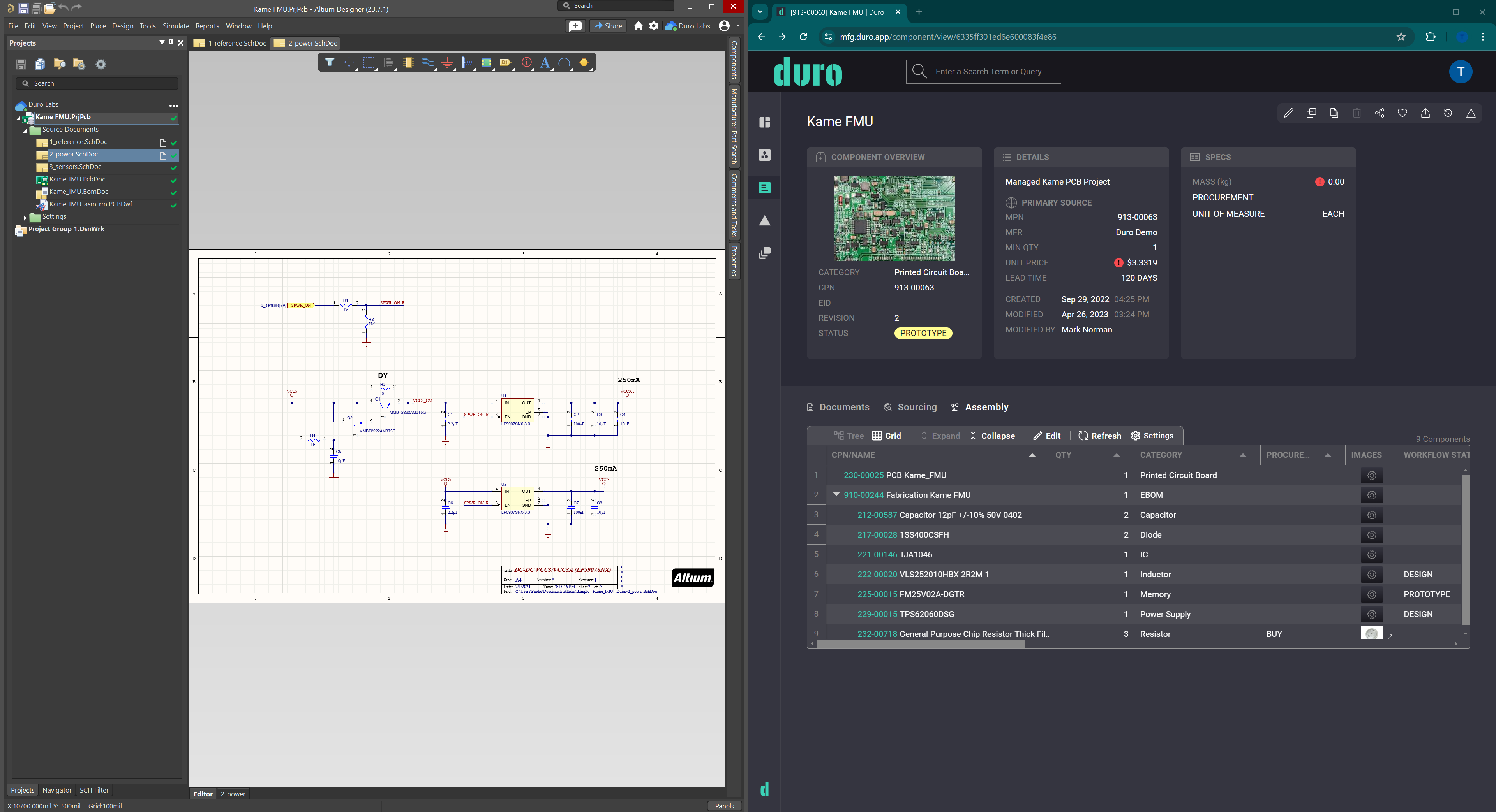
ECAD (Electronic Computer-Aided Design) focuses on designing and developing electronic systems, such as printed circuit boards (PCBs). ECAD software helps engineers create schematics, simulate circuit behavior, and generate layouts for manufacturing.
Key ECAD functions
- Schematic Design: Mapping how electronic components connect and interact.
- PCB Layouts: Translating schematics into physical board layouts with precise component placement and trace routing.
- Circuit Simulation: Allowing engineers to predict circuit behavior without needing a physical prototype.
ECAD software such as Altium 365 streamlines collaboration by enabling engineering teams to manage and share schematic and PCB designs in the cloud, ensuring version control and real-time access to design data.
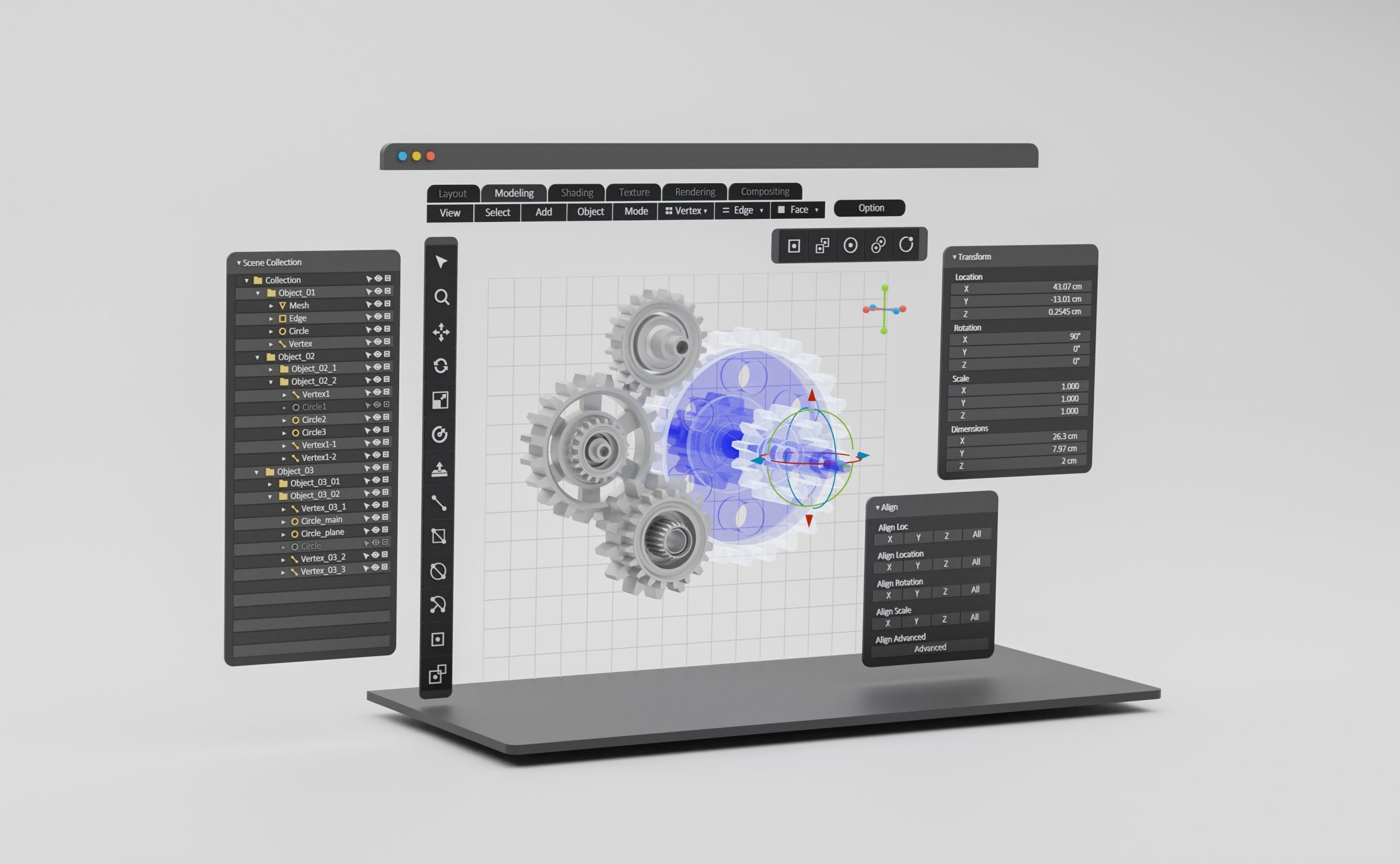
What is MCAD Software?
MCAD (Mechanical Computer-Aided Design) is used to design mechanical components such as enclosures, mounting hardware, and other physical structures. MCAD software enables engineers to create 3D models, test mechanical performance, and generate manufacturing documentation.
Key MCAD functions
- 3D Modeling: Creating detailed physical structures using parametric or direct modeling.
- Assembly Modeling: Ensuring all parts fit together correctly and checking for mechanical interferences.
- Mechanical Simulation: Testing designs for factors like stress and motion to ensure reliability.
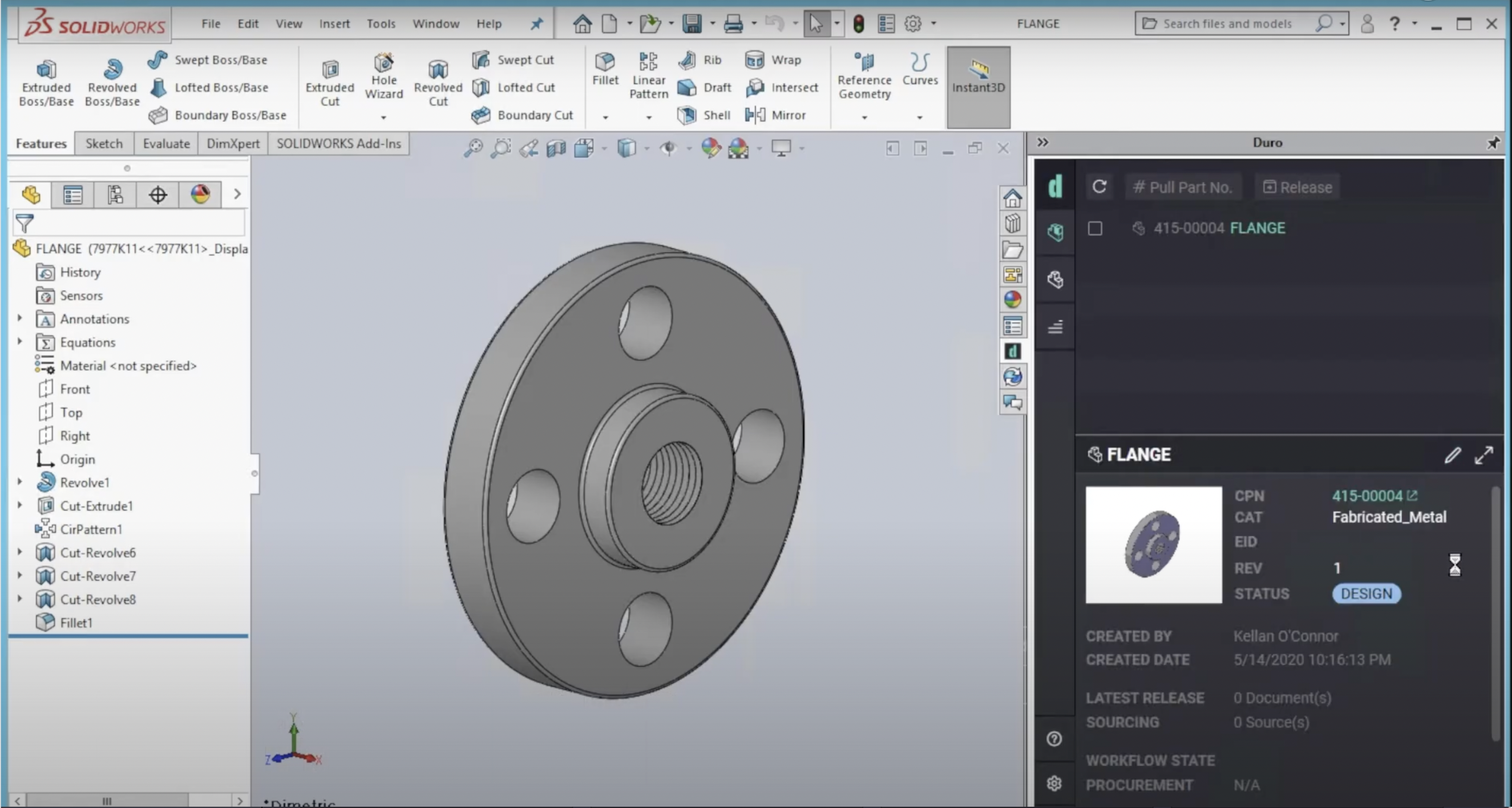
Engineering teams use MCAD software like SolidWorks, Onshape, and Siemens NX to optimize designs for manufacturability and functional performance.
ECAD vs MCAD and how they work together
Although ECAD and MCAD software focus on different design aspects, they need to work cohesively to ensure the final product functions as intended. A hardware tech stack will typically use upstream MCAD and ECAD tools to develop and refine their product design and to create a bill of materials.
ECAD handles the electronic components and circuit designs, while MCAD focuses on the physical structures that house and support those components. Despite their differences, both must align perfectly for the product to function as intended.
Integrating ECAD and MCAD requires tools capable of synchronizing data between the two domains, which is where Product Lifecycle Management software plays a key role. PLM centralizes and synchronizes data, ensuring teams can collaborate effectively and manage real-time design revisions, BOMs, and product updates.
How ECAD, MCAD, and PLM work together
Integrating ECAD, MCAD, and PLM is essential for efficient hardware development, especially as engineering teams increasingly adopt cloud-based tools. PLM systems are the backbone of a hardware tech stack, connecting these tools by centralizing product data and facilitating real-time collaboration across engineering teams. This ensures teams can manage BOMs, change orders, and revisions effectively while bridging the gap between disparate ECAD and MCAD systems.
For example, a PLM integrated with SolidWorks for MCAD and an ECAD tool like Altium 365 ensures consistent design data across both domains. This type of integration helps teams keep electronic and mechanical designs in sync, reducing errors and enabling more efficient product development.
ECAD and MCAD challenges and how PLM helps
Data Silos
ECAD and MCAD tools often operate in separate cloud environments, leading to isolated data that makes cross-discipline collaboration challenging. PLM eliminates these silos by centralizing data from both systems, making it easily accessible and ensuring that all teams have real-time visibility into the design process.
Version Control Issues
Managing revisions across multiple PDM systems can result in conflicting design versions, leading to errors, delays, and costly rework. PLM provides a unified platform that ensures version consistency across both ECAD and MCAD tools, so all teams are always working with the latest design data
Collaboration Bottlenecks
Electrical and mechanical engineering teams often follow different workflows, which can create communication inefficiencies. PLM streamlines these workflows by integrating ECAD and MCAD data into a single system, enhancing collaboration and speeding up the product development process.
Simplify ECAD and MCAD Software integration
Both ECAD and MCAD software are central to today’s engineering teams in helping them design more complex hardware products. ECAD supports the electronic aspects, like PCB layouts, while MCAD focuses on the mechanical side, such as enclosures and mounting hardware. For a product to work effectively and get to market on time, the electronic and mechanical designs must align, which requires strong collaboration between the two.
Duro’s PLM was designed with this in mind and equipped with the leading ECAD and MCAD tools. Duro ensures that electrical and mechanical engineering teams can work from the same platform, keeping design data synchronized and accessible in real-time. This means no more data silos or version control headaches, making it easier for engineers to stay on the same page.
With Duro, companies can streamline their design processes, reduce costly errors, and bring their products to market faster. Duro provides a flexible, lightweight solution for managing both ECAD and MCAD workflows in one place, helping teams collaborate more effectively and focus on innovation rather than chasing down misaligned data.